1. Dislocation Dynamics Simulations
Predicting the mechanical behavior of a structure through simulation has the advantage that it is cheaper than the experiment and can measure challenging values (stress concentration, dislocation density, etc.). Classical continuum theory is widely used as a basic theory for predicting, designing, and analyzing the behavior of macrostructures such as automobiles and ships. However, classical continuum theory does not correctly predict the behavior of small structures. The behavior of structures predicted by classical continuum theory is much more flexible than the behavior of actual structures obtained from experiments.
Dislocation dynamics (DD) simulation is a technique for predicting the structural behavior of hundreds of nanometers to tens of micrometers. The structure is modeled as a continuum, and the dislocation is modeled as line singularity. Dislocations are created and moved by continuum mechanics. Dislocation affects the entire structure modeled as a continuum. Therefore, DD simulation can be said to be a technique for predicting the plastic behavior of materials by properly combining continuum mechanics and dislocation mechanisms. Using DD simulation, various mechanical behaviors such as dislocation structure, structural behavior between hard layer and material, yield stress, and strain-hardening rate according to the size of the structure can be calculated.
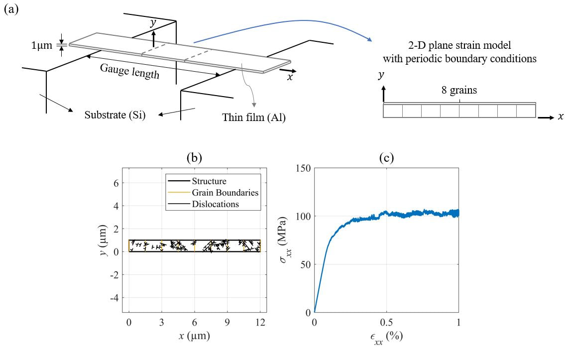
(a) A 2-D plane strain DD simulation model for an Al thin film tensile test, (b) Dislocation structures, and (c) Stress-strain curve.